Prior to selecting an RTD configuration, it is important to know just how RTDs are ‘read’. RTD temperature sensors (and strain gauges for that matter) may be thought of as variable resistors. Their electrical resistance changes as they are compressed/stretched (strain gauges) or heated/cooled (RTDs). One of the great things about RTD sensors is that they provide an absolute temperate. They don’t report an offset from a cold-junction like a thermocouple. The resistance of a PT100 sensor is 100 ohms in freezing water, no matter what temperature the wiring, connectors, or the device reading the sensor is.
Sensor resistance is measured by passing a small, known, current through the device. Ohm’s Law states that voltage equals current times resistance, which means the measured voltage across a sensor will be proportional to its resistance. If the resistance of the wires between the sensor and the measuring device is low, and the sensor resistance is relatively high, the lead resistance may be ignored. If, however, the sensor resistance is relatively low or the lead resistance is high because (the lead wires are long) the lead wire resistance can introduce significant measurement error. What measurement configuration is chosen all comes down to a balance between the number of wires (cost) vs the required measurement accuracy/
Regardless of the number of wires connected between a resistive sensor and the MI-8, four MI-8 pins are used. Excitation current flows out through the Ex+ pin and into the Ex- pin. Voltage is measured between the + and – pins. Each sensor uses unique Ex+, + and – connections. The Ex- pin is shared for all resistive sensors. The An1 analog input doubles as the Ex- pin for resistive measurements and cannot be used as an analog voltage input when the MI-8 is configured to measure resistive sensors. The MI-8 supports two, three, and four wire connections to sensors.
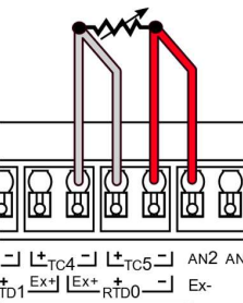
4-Wire Connection
Four-wire connections, also known as Kelvin connections, provide the most accurate resistance measurement. Electrical current flows through the Ex+ and Ex- wires while the + and – leads are only used to measure the voltage across the sensor. The Ex+/+ and Ex-/- leads are then connected at the sensor itself. Since no current flows through the + and – leads, any electrical resistance in the sensor wiring will not result in a voltage drop on those wires and will not lead to measurement error. The advantage here is that the wires no longer need to be the same length or even the same type for accurate measurements.
The down side is that all four wires must be run between the sensor and the measuring device which can mean additional cost.
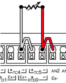
2-Wire Connection
Two-wire connections make running wires cheaper and simpler for applications where precision can be sacrificed to varying degrees. Some applications see minimal degradation in measurement. For instance, applications where the RTD probe is within inches or a few feet of the sensor board. In this case, wire resistance is not high enough to interfere with (offset) the reading of the RTD element. In other cases, precision requirements are low enough that using even long wires is not an issue. In these cases, two-wire may be sufficient.
Two-wire sensor connections use the same wires for excitation current and voltage measurement. Since current flows through the wires there will be a voltage drop and that drop will result in a measurement error. The measurement system not only measures the resistance of the sensor, but also the leads between the DAQ and sensor. If the wire resistance is small or the wire length is short this error may be negligible.
When using a two-wire connection both the Ex+ and + and the Ex- and – pins must be connected together as close to the MI-8 connector as possible
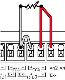
3-Wire Connection
Three-wire connections represent a compromise between four and two-wire connections. Three-wire measurements can be more accurate than two-wire if the resistances of each of the three wires are closely balanced. The advantage here is cost. Running three wires to a sensor is generally cheaper than running four.
The MI-8 compensates for lead wire resistance by measuring the resistance between the Ex- and – leads, then subtracting that value from the sensor resistance measurement. This means all three wires must be the same length and type, otherwise the MI-8 three-wire compensation could actually make the measurement worse.
When using a three wire connection, the Ex+ and + pins must be connected together as close to the MI-8 input connector as possible
Conclusion
While four-wire Kelvin connections provide the most accurate measurements for strain gauges and RTD sensors, three and even two-wire connections can still provide acceptable results depending on the application and its requirements. For design advice or for more information feel free to reach out to us at Technical Support, we’re happy to help.